Build Your Own
If you'd rather build your own SysLat device than purchase one, here are your instructions to do so.
SysLat currently works with Arduino-compatible Boards including the Arduino Uno and Adafruit's Itsy-Bitsy 32u4 (5V version). It should be easily ported to any development board that has on-board USB with a serial COM port. If you'd like to help us get the system up and running on other types of boards such as Raspberry PI, please take a look at the SysLat_Firmware repo and submit your pull request!
The theory of operation is pretty straightforward, so ports to other microcontrollers with similar specs should yield similar measurements. But we are interested to find out how it runs on different boards/microcontrollers. Also, mounting the device to the monitor and shrouding the sensor from ambient light will be left as an excercise for the reader. Please share pics of your completed device over on r/SysLat!
Getting started
To follow this guide you'll need: [TOOLS]
- Soldering Iron and solder - we recommend 0.031" (.8mm) diameter
[HARDWARE]
- Adafruit ItsyBitsy 32u4 5V 16MHz or your Arduino-compatible board of choice
- A breadboard and jumper wires
- A phototransistor (light sensor), such as this one: https://www.digikey.com/en/products/detail/everlight-electronics-co-ltd/ALS-PT204-6C-L177/2675510
- A resistor in the range of 200K to 500k ohms. If your monitor has really crummy contrast ratio, you may want to go a bit lower still, such as 100k.
- Something to put around the phototransistor to shield it from external ambient light
- An 8 digit LCD (optional - can easily be changed to work with different size LCD screens)
[SOFTWARE]
- The Arduino IDE (more instructions below)
- Syslat PC Software and RTSS: https://syslat.com/downloads
Wiring Up the Main components
The image below shows how the photosensor and resistor should be connected. Vout is the node that will connect to the D7 pin on the ItsyBitsy. In this configuration, the voltage at Vout will be held low, near 0V, until enough light strikes the sensor, causing current to flow and the voltage will rise to nearly 5V.

Here is the overall pinout showing where the pins are on the ItsyBitsy board. It also shows the pins used for connecting the optional character LCD screen.

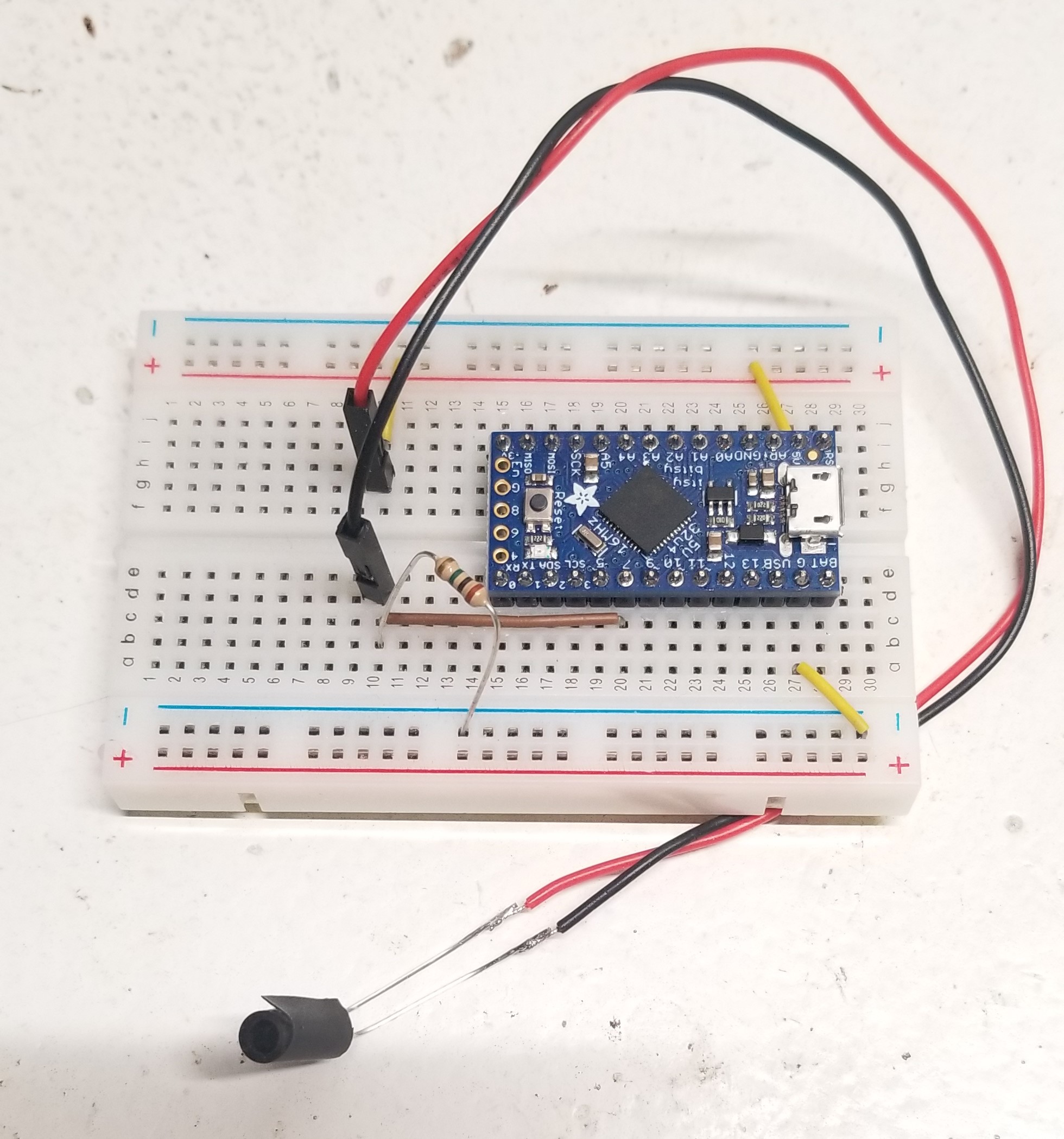
Below is an example showing the basic wiring for the sensor:

Installing the Optional LCD
Here is the Itsy pinout with a small LCD's pin diagram and info. This is the same LCD used in Syslat monitors we build.
For this particular LCD, a 200 ohm resistor is needed from +5V to the LCDs power pin. Make sure to check the datasheet of your LCD of choice when hooking it up for details such as this.

Here it is wired to the breadboard:

Loading the Firmware
This step is a bit basic, but we're including it for any beginners that are taking part. // need to include LCD declaration for this version in firmware (pinout is different)
- Download/clone the SysLat_Firmware repository
- Download and install the Arduino IDE
- Open the Arduino IDE
-
Go to the "Tools" menu and choose the correct board type (in this case "AdaFruit ItsyBitsy 32u4 5V 16MHz") as shown in this screenshot. Note that if you do use this adafruit board, you will need to follow a few steps to get it set up with Arduino: https://learn.adafruit.com/introducting-itsy-bitsy-32u4/arduino-ide-setup and: https://learn.adafruit.com/introducting-itsy-bitsy-32u4/using-with-arduino-ide

-
Choose the correct COM port that represents your device as shown in this screenshot. If you run into an error at this step please reach out to us at support@syslat.com.

-
Upload the file to the board.

-
Feel free to reach out to us with any questions at support@syslat.com. Good luck and enjoy building your new tool!